20+ led driver block diagram
Q111 -33V FAST OFF CIRCUIT Q109 Block diagram. This Circuit can be build as 20 Watt or 10 Watt White LED Tube Light.
Block Diagram Of An Led Driver Using Proposed Dcl Download Scientific Diagram
Found inside Page 24VOLTAGE DRIVER Q 106 -DRIVER Q117 db March - April 1986 24 db March - April.

. The linear constant current regulator is a simple economical and robust device designed to provide a cost effective. Ad LED Drivers Designed to Power the Next Generation of ACDC LED Lighting Applications. 230 Volt AC Direct LED Tube Light Driver Circuit designed with few easily available components.
AN3981 STP04CM05 - 4-bit LED array driver Doc ID 022217 Rev 1 754 previous status if the junction temperature falls typically 15-20 C below the thermal shutdown threshold. The EN input allows the LED array to be turned on EN greater than 15 V or off EN less than 04 V or dimmed using a PWM signal. 35 Overnight Ship on All Orders.
The PCA9626 is an I²C-bus controlled 24-bit LED driver optimized for voltage switch dimming and blinking 100 mA RedGreenBlueAmber RGBA LEDs. LED Driver Constant Current Regulator 20 mA 45 V. Ad Over 5 Million Electronic Parts from Leading Manufacturer Brands.
A constant-voltage and constant-current CV-CC controller is adopted to sense the output. Driver Block Diagram 17 Setting the LED Current and Analog Dimming. LED Driver 4-Channel 6 Watt with Diagnostics r rFAN5702.
Over 5 Million Parts Available Online. 120V AC Dimmable LED Driver AL1692EV1. 20 watt led driver circuit diagram.
Each LED driver block has a connector that allows for flexibility of design in testing UDIM and SDIM. EV Charging Block Diagram AUX Power Isolation LCD Backlighting Voltage Sense µCU Gate Driver Main DC-DC Current Sense. Driver For 20 LEDs Circuit Diagram.
A typical 120V 60Hz household outlet provides the input to the system. Each LED output has its own 8-. In this matrix we can select any LED by.
Transformer Winding Construction Diagram Item Winding name Description 1 WD1-Primary Winding Start at Pin8 Wind 180 turns of Φ03mm. ICE40 LED Driver User Guide Technical Note FPGA-TN-02021-15 November 2021. Scalable Solutions Help Reduce Design Time and Complexity.
20 mV -VIN -OPT Diode Emulation Comparator V N. Functional Block Diagram of TPS92515HV-Q1. Additionally Figure 7 shows the proposed LED streetlight driver with control block diagram.
Figure 3 shows a block diagram of the TPS92515HV-Q1 buck LED driver. Output of the system is the light produced by the LEDs. 20 led display block diagram Wednesday September 14 2022 Edit.
Figure 4 shows the Level 0 block diagram for the LED Driver. Download scientific diagram Block diagram of LED panel.
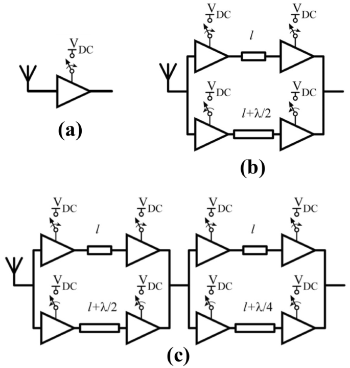
Low Resolution Architectures For Power Efficient Scaling Of Mmwave Phased Array Receivers Springerlink

Typical Block Diagram Of An Led Driver Download Scientific Diagram
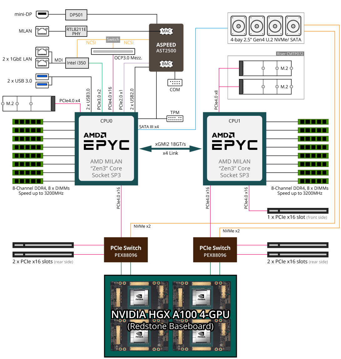
G262 Zl0 Rev A00 Gpu Servers Gigabyte Global
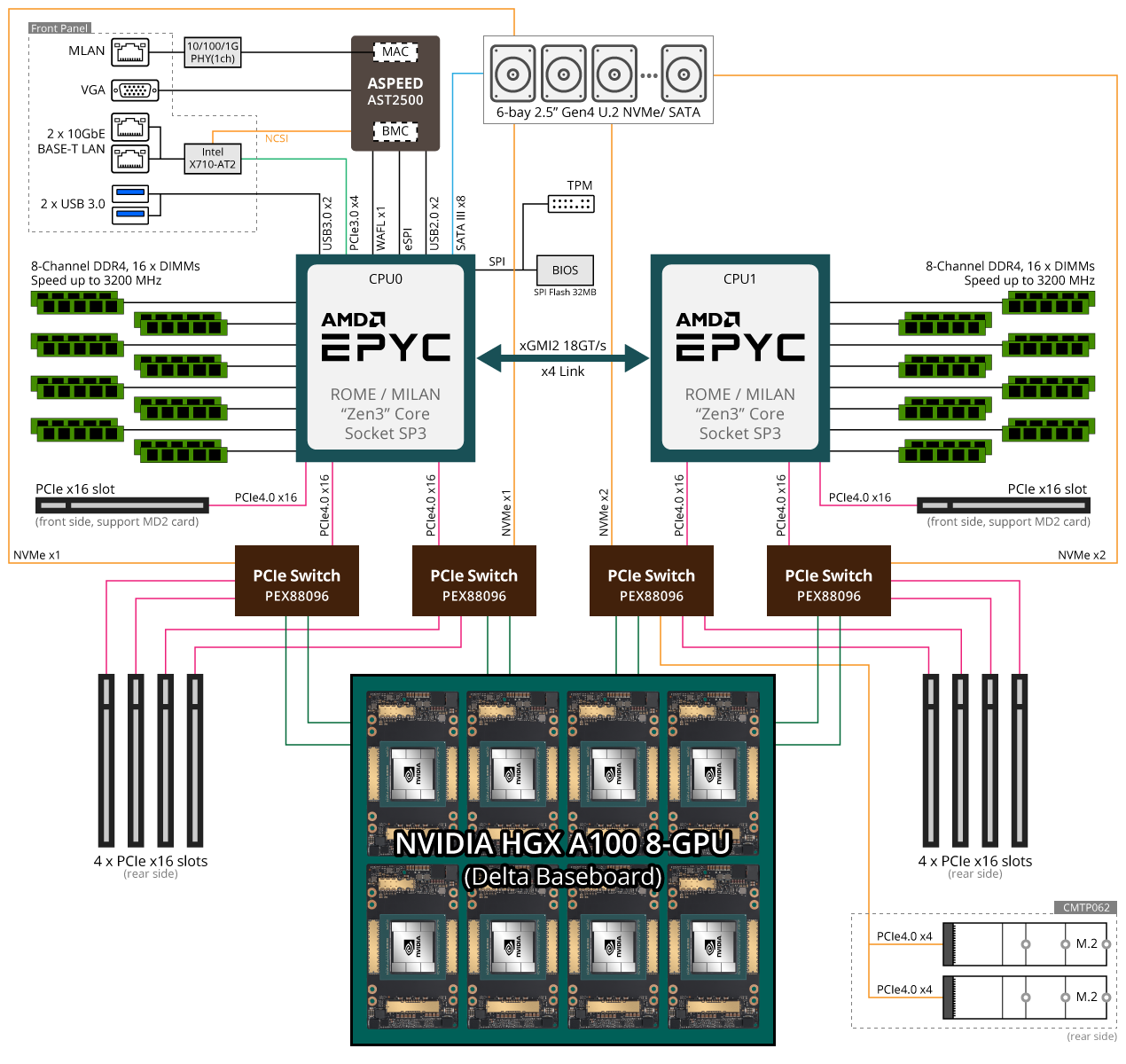
G492 Zl2 Rev A00 Gpu Servers Gigabyte Global

Ex99 2 32 Jpg

Ex99 2 18 Jpg

Block Diagram Representation Of The Led Driver Download Scientific Diagram

The Proposed Led Streetlight Driver With Control Block Diagram Download Scientific Diagram
Diy 8 Bit Handheld Multiplayer Gaming Device Medium
Led Driver Asic Schematic And Input Output Signal Timing Diagram Download Scientific Diagram
Ex99 2 21 Jpg

Stiebel Eltron Tempra 20 Plus Advanced Flow Control Self Modulating 20 Kw 3 90 Gpm Compact Residential Electric Tankless Water Heater Tempra 20 Plus The Home Depot

Pin On Electronique

My Cell Phone Jail For Middle School This Year Middle School Science Classroom Teacher Hacks Cell Phone Jail
_KGlISZ6SfV.jpg)
How To Build 8x8x8 Led Cube Arduino Project Hub

Block Diagram Of Constant Voltage Fed Dual Purpose Led Driver Download Scientific Diagram

Block Diagram Of The Proposed Led Driver System Download Scientific Diagram